A professional LED screen installation runs through nine phases: site assessment, hardware selection and logistics, mounting structure, panel installation, electrical integration and safety testing, calibration, content system integration, documentation and training, and maintenance planning. This guide explains what each phase checks, with typical values and tolerances, and the rules that apply in Switzerland.
On this page
Key takeaways
- Calibration is the step that decides whether a wall reads as one screen or as many panels
- LED walls weigh roughly 25–60 kg/m² depending on technology and pitch, and outdoor installations with weatherproofing can exceed 500 kg, so the load-bearing capacity of the wall, ceiling or floor is checked first
- At maximum brightness, plan for roughly 300–600 W/m² indoors and 800–1’200 W/m² for high-brightness outdoor screens, plus a 20–30% safety margin
- Critical tolerances: flatness ±2 mm, level ±0.1°, brightness uniformity ±3% after calibration
- In Switzerland, the ESTI rules for electrical installations, cantonal and municipal building codes, fire safety requirements and local rules on light emissions are checked before installation
For market context, Grand View Research (June 2026 edition) estimates the global Digital Signage market at USD 31.1 billion in 2025 and projects USD 58.4 billion by 2033, a compound annual growth rate (CAGR) of 8.2%.
Phase 1: site assessment and pre-installation planning
Structural analysis
Before any installation begins, a thorough structural assessment determines whether your location can safely support the intended LED display. LED walls can weigh between 25 and 60 kg per square metre depending on technology and pitch. A 10 m² indoor wall might weigh 350 kg, while outdoor installations with weatherproofing can exceed 500 kg.
Engineers evaluate:
- Wall load capacity for surface-mounted installations
- Ceiling structure for suspended or flying configurations
- Floor reinforcement needs for freestanding structures
- Anchor point availability and spacing requirements
For retrofit projects in existing buildings, structural calculations often require approval by a structural engineer. New constructions should specify LED mounting requirements during the design phase.
Electrical infrastructure
LED displays demand significant electrical capacity. A typical indoor display consumes roughly 300–600 W/m² at maximum brightness, while outdoor high-brightness screens may require 800–1’200 W/m². To keep this consumption down, see our guide to energy-efficient LED displays. Key electrical considerations include:
- Total power requirement with a 20–30% safety margin
- Dedicated circuit breakers separated from general building systems
- Three-phase power for larger installations (typically above 15 kW)
- Voltage stability requirements (±5% tolerance typically specified)
- UPS backup recommended for critical applications
Environmental conditions
Ambient conditions directly affect display selection and the installation approach:
- Temperature range: indoor displays typically operate between 0 and 40 °C; outdoor units handle −20 °C to +50 °C
- Humidity levels: most displays tolerate 10–80% relative humidity, non-condensing
- Dust and particles: the IP rating determines the level of protection (IP20 indoors, IP65 or higher outdoors)
- Direct sunlight exposure: affects brightness requirements and thermal management
- Vibration sources: nearby machinery or traffic may require damping solutions
Network and control infrastructure
Modern LED installations require robust connectivity:
- Ethernet cabling (Cat6, or fibre for long runs) to each display zone
- Control room location with adequate HVAC and access
- Backup connectivity options for mission-critical displays
- Integration points with building management systems
Phase 2: hardware selection and logistics
Matching technology to environment
The site assessment sets the final hardware specifications: an indoor or outdoor rating, the brightness needed for the ambient light, a pixel pitch suited to the viewing distance, and a weight and power budget the building can carry.
Logistics coordination
Professional installation requires careful logistics planning:
- Delivery scheduling to minimise storage time on site
- Equipment staging area with climate control for sensitive components
- Access routes for heavy or oversized panels
- Crane or lift requirements for elevated installations
- Security arrangements for high-value equipment
Phase 3: mounting structure installation
Frame construction
The mounting structure forms the foundation of any LED installation. Common approaches include:
Wall-Mounted Systems
- Steel bracket arrays anchored to structural members
- Levelling adjustments for precise alignment
- Service access provisions for front or rear maintenance
Freestanding Structures
- Custom steel or aluminium frames designed for specific loads
- Anti-tip measures for public safety compliance
- Integrated cable management channels
Suspended (Flying) Configurations
- Rigging calculations certified by structural engineers
- Redundant hanging points for safety
- Easy lowering mechanisms for maintenance access
Precision requirements
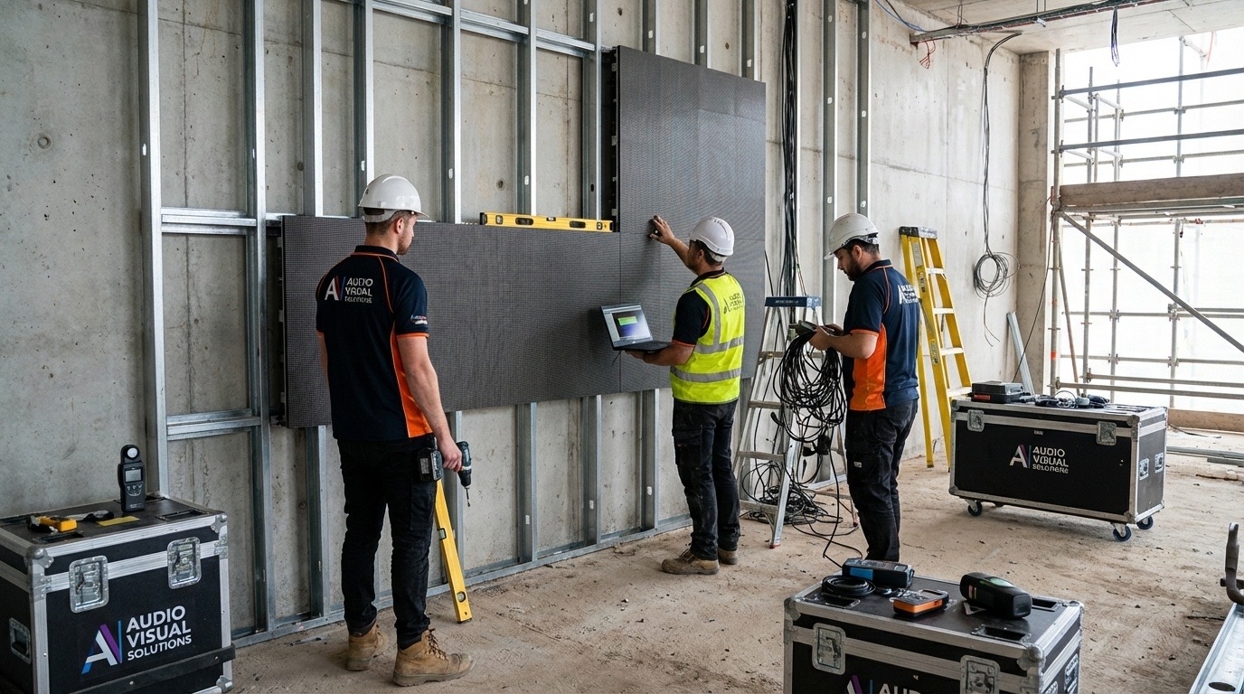
LED panel alignment tolerances are measured in millimetres. The mounting structure must achieve:
- Flatness: ±2 mm across the entire display surface
- Level: ±0.1° horizontal and vertical deviation
- Square: diagonal measurements matching within 3 mm
Laser levelling and surveying equipment ensures these tolerances during frame installation.
Phase 4: panel installation and connection
Panel mounting sequence
LED panels are installed systematically, typically following a pattern that minimises visible seams:
- Start from a fixed reference point (usually the bottom-left corner)
- Install row by row, ensuring horizontal alignment
- Verify alignment after every 4–6 panels
- Document panel serial numbers by position for future reference
Interconnection process
Each panel requires multiple connections:
- Power connections with proper polarity and earthing
- Data connections to the LED controller, usually over the control system’s own protocol
- Mechanical locks securing panels to the frame and each other
Cable management
Professional installations feature invisible cable routing:
- Cables labelled at both ends for easy troubleshooting
- Service loops allowing panel removal without disconnection
- Strain relief preventing connection fatigue
- Fire-rated conduit where fire regulations require it
Phase 5: electrical integration and safety testing
Power distribution
Large installations use a distributed power architecture:
- Main distribution board with per-zone circuit protection
- Power sequencing to prevent inrush current damage
- Voltage monitoring with automatic shutdown on anomaly
- Earthing verification ensuring electrical safety
Safety testing protocol
Before the display is powered up, certified electricians verify:
- Insulation resistance testing on all circuits
- Earth continuity measurements
- RCD (residual current device) functionality
- Emergency stop system operation
- Fire suppression system integration where applicable
Phase 6: system configuration and calibration
Controller setup
The video processor or controller requires careful configuration:
- Resolution mapping matching native panel resolution
- Input source assignment for each display zone
- Colour space settings (sRGB, DCI-P3 or custom)
- Brightness scheduling for day and night operation
Pixel-level calibration
Factory calibration provides a baseline, but on-site calibration optimises performance:
Brightness Uniformity
Using calibrated measurement equipment (colorimeters), technicians adjust the brightness of individual cabinets to achieve ±3% uniformity across the display surface.
Colour Calibration
Professional calibration targets specific colour standards:
- White point: typically D65 (6’500 K)
- Gamma: 2.2 or 2.4 depending on ambient light
- Colour gamut: sRGB minimum, DCI-P3 for premium applications
Seam Correction
Slight brightness variations at panel edges create visible seams. Advanced controllers apply compensation curves to minimise these artefacts and keep the image seamless.
Phase 7: content system integration
CMS connection
The display connects to your content management system:
- Network configuration with static IP or DHCP reservation
- Security settings including firewalls and access controls
- Scheduling system integration for automated content rotation
- Configuration of optional sensors for anonymous audience measurement, if required
Testing content playback
Before handover, verify:
- Resolution accuracy with test patterns
- Frame rate smoothness at 60 Hz minimum
- Colour accuracy against reference images
- Audio synchronisation where applicable
- Failover behaviour when the content source is interrupted
Phase 8: documentation and training
As-built documentation
Complete project documentation includes:
- Installation drawings with exact dimensions and mounting points
- Electrical schematics showing all circuits and connections
- Network diagrams with IP addresses and access credentials
- Panel mapping showing serial numbers by position
- Calibration records with measurement data
- Warranty information and service contacts
Operator training
Trained staff ensure ongoing system success:
- Basic operation including power-on/off procedures
- Content management using the CMS platform
- Troubleshooting common issues and escalation paths
- Maintenance scheduling and cleaning procedures
- Emergency procedures for system failures
Phase 9: maintenance planning
Spare parts strategy
Keep critical spares on site, or agree their availability with the supplier:
- LED panels: 2–5% of total count
- Power supplies: 1–2 units per zone
- Receiving cards: 1–2 per display
- Cables and connectors: assorted replacements
Swiss-specific considerations
Installations in Switzerland must comply with:
- Regulations of the Federal Inspectorate for Heavy Current Installations (ESTI) for electrical installations
- Building codes varying by canton and municipality
- Local rules on light emissions, which can restrict outdoor display brightness at night
- Fire safety requirements for public venues
- Accessibility standards ensuring displays don’t obstruct pathways
Why professional installation matters
While DIY approaches may seem cost-effective, professional installation delivers:
- Optimal performance through proper calibration
- Safety compliance with local regulations
- Faster troubleshooting from documented systems
- Extended lifespan through correct thermal management
HYPERVISUAL’s installation teams handle projects across Switzerland and Europe, from compact retail displays to large-scale architectural installations. Our turnkey installation service covers coordination with the structural engineer, installation, calibration and ongoing support, and we visit the site if necessary.
Two installation lessons from our projects
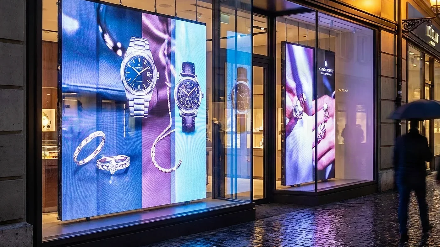
For the jeweller’s boutique network described in our case study on presence detection behind two-way mirrors, every frame was assembled before it ever reached a boutique: panel, player, camera, power supply and a single cable, mounted on rails inside a wooden frame lined with black felt. Shop windows leave no room for improvisation and no second chance during opening hours: pre-assembly turns a delicate on-site build into a controlled fitting.
In a design study for an international brand equipping temporary retail spaces, described in our case study on a network of ten pop-up stores, the structuring decision came even earlier. Instead of designing the furniture and then hunting for a screen that fits, the exact panel dimensions (frame, visible area, thickness) were frozen first, then passed to the design office so that the structures were built around the display. On integration projects, the order of decisions matters more than the choice of brands.